Last
updated: 7-Sep-05, 11:12:16
PM
Tweaking the Futaba 9Z
Please
note:
This
page may take a while to load due to the large amount of photographs.
Most
Futaba radios have a formerly secret service menu implemented into their
firmware. This menu was designed for transmitter testing and servicing, but
also allows a degree of radio customization.
One
of the greatest features available through the service menu is the ability to
customize the toggle switches (switch A through to switch H). In fact any
combination is possible including the ability to swap switches such as Idle-Up
and Thro-Hold or any other pair. This also makes possible the installation of
3-position switches to any 9Z radio allowing an identical switch configuration
with the latest 9Z WC2.
In
fact there are only 3 things that differentiate a WC2 from its predecessor WC
- The new
blue colour, and stronger switch bases
- Switches
A,B and D now offer a middle (third) position
- A
slightly improved firmware that offers the so-called “accelerated frame
rate around centre“, which improves the response of the fourth digital
servo in 4-servo CCPM implementations.
Thus if you are not flying 4-point CCPM
helicopters fitted with digital servos this simple switch conversion could
really give you all the benefits of the new WC2 system. Not to mention that the stronger switch
bases, blue stick and stickers are available from Futaba service centres. Isn’t
it time to give your radio a new look?
The
9Z has numerous other service menu functions which allow quick testing of the
radio’s electronic and mechanical components such as sticks, knobs, slides,
switches, trims, voltmeter and tachometer. Additionally, one could also see the
firmware version, the radio’s total usage time and most importantly, retrieve
the password which is commonly forgotten.
I
have received a number of emails from people who bought a second-hand 9Z
transmitter and were seeking advice on how to convert from stick mode 1 to 2 or
the opposite. The physical conversion is relatively simple for someone who can
carefully unplug a few cables and lift one of the PCBs (*).
However, once the physical alternations are made it is necessary to recalibrate
the sticks due to elevator and throttle having different amount of travel. If such calibration in not performed the
unwanted effects include increased elevator servo throw (beyond the radio’s
specifications) and throttle/pitch curve points 1,2,12,13 becoming unreachable.
Again the service menu will allow you to perform such a task (**).
Calibration
is not only required when a stick mode conversion is performed. In the short time
that I have owned a 9Z I noticed that slight drifts have developed to the
neutral positions due to normal wear of the joystick potentiometers. Factory
calibration may also be lost when the lithium back-up battery is replaced.
Non-calibrated
stick neutral positions may cause various unwanted effects such as small
aileron, elevator or rudder servo movement upon activation of Dual Rates (D/R).
This undoubtedly changes in the aircrafts trimming upon activation of D/R and
becomes more obvious at low values of D/R.
If
you are unsure to whether your transmitter’s sticks are correctly calibrated or
not, you can perform this simple test.
- Start by
selecting a blank (freshly reset) airplane program.
- Go to the
ATV menu
- Hold both
sticks fully up and fully right while switching between AIL, ELE, THR and
RUD. If the pointer below the graph moves even a little while you are
switching channels you radio needs calibration.
- Repeat
step 3 but now holding both sticks fully down and fully left.
- Finally,
repeat step 3 with both sticks cantered (including throttle axis).
People
often ask how to convert the default transmitter program from airplane to
helicopter (or vice versa) or how to change the default stick mode between 1
and 2. Such conversion requires the replacement of a resistor (R133) and once
done a complete hardware reset is required for the changes to take effect. Such
reset erases all stick calibration values, thus we again need access to the
service menu to recalibrate the radio. The picture below will help you identify
the part that needs to be replaced. If you cannot find a replacement SMD
resistor (package type 0805) you can use any standard size resistor. Also you
may use a piece of wire instead of a zero-ohm resistor.
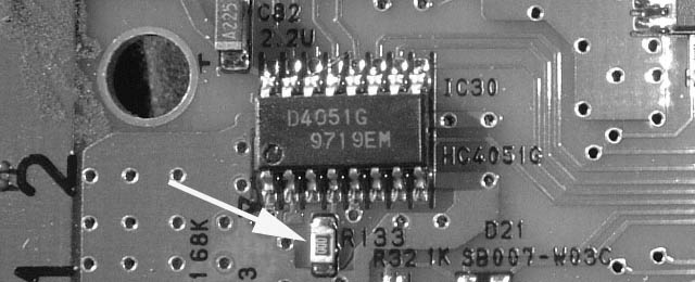
No.Resistor (open circuit) =
stick mode 1, T9ZHP (heli)
68K (labelled 683) = stick mode 2, T9ZHP (heli)
18K (labelled 183) = stick mode 1, T9ZAP (air)
Short (labelled 000) =
stick mode 2, T9ZAP (air)
Added
The
complete hardware reset is performed by shorting two pads on the 9Z processor
circuit board. These can be reached via two small holes at the bottom of the
battery compartment, thus disassembly of the transmitter is not necessary. The
pads need to be shorted for a couple of seconds using a piece of wire. A
paperclip works well. On the next power on the transmitter will display a
warning message. Powering the transmitter off and back on will clear this.
Following a hardware reset the joysticks will need to be recalibrated as
described below. Note that the hardware reset erases all data from the
transmitter including model programs, thus a copy needs to be made to a CAMPac,
UltraPAC or equivalent storage card.
Added
Below
you will find detailed explanation of each of the service menu screens. Access
to the service menu can be obtained using our UltraPAC. See the products
page for details.
If
you have any questions regarding these modifications or issues not discussed
here please do not hesitate to contact me. Remember, when any alteration is
performed to your radio system, regardless of how minor, you are strongly
advised to carry out a full check of the controls prior to operating each of
your models.
Finally,
if you would like to see a personal message from the developers of 9Z go to the
voltmeter screen and press [L] and [M] simultaneously. Once the first message
appears you may press [L] and [M] again which brings a second message up.
Happy
flying!
-Angelos
(*) Physical conversion of the stick mode requires
disassembly of the transmitter which includes temporary removal of one circuit
board. However, once access to the rear of the joysticks is possible,
conversion can be performed fairly easy. People often mistaken and swap the two
joysticks around. This is not required and in fact will cause confusion as the
stick positions will no longer correspond to the trims and to what is shown on
the screen of the transmitter. If you take a careful look at the joystick
mechanics you will notice that the throttle axis has a spring too which is
retained extended by a plastic tab to prevent automatic centring of the
throttle. There are also two limiters that reduce its full through. All that is
required for the stick mode conversion is to remove the tab and the two
limiters and install them at the other joystick. At this point you have two options. The first
one involves the replacement of R133 (see above) which will result in a perfect
conversion where your radio will function as if it was manufactured for this
new stick mode. Your second option is to proceed without replacing R133.
However, you will still need to calibrate the sticks as J2 and J3 now have
different through than before. Additionally, since R133 is not replaced the
transmitter is not aware of the new stick layout, thus every time you create a
new model program (or reset a model program) you will have to go to FNC menu
and manually define how the sticks and trims are coupled with the output servo
channels.
(**) Futaba distributors in USA found a quick way to
resolve this issue without revealing the service menu. They recommend a full
hardware reset. Such reset erases all calibration parameters and loads some
default values. These default values are approximate values for any newly
manufactured transmitter and they represent calibration values of both elevator
and throttle being of short stick travel. This procedure will resolve the
problem of throttle/pitch curve points being unreachable, however the increased
elevator servo throw will remain. The reset will also wipe the factory
calibration of the voltmeters, in which case the voltmeters will continue to
function but they may have reduced accuracy. Loss of neutral point calibration
may also affect the aircraft’s trimming upon activation of Dual Rates as
discussed above.
Added 15 Dec 2002:
Great news! Last night I discovered that my 9Z-WC in fact transmits a 10th
channel! Channel 10 is non-proportional just like channel 9 and is permanently assigned
to switch-D. The signal for channel 10 is produced by the PCM decoder chip
(FR6302B) and available inside the receiver (pointed by the yellow arrow
below). It can be accessible externally with an easy and inexpensive
modification. All you need is a 470 Ohm resistor, a 470pF capacitor and a servo
socket. Have a look at the DIY page to see how I did it on my
FP-R129DP receiver.
So
why didn’t Futaba call it 10Z?
Added 29 Dec 2002: The
“accelerated frame rate” feature of the latest 9Z WC2 has been broadly
discussed at various internet newsgroups, yet very little information was given
out by Futaba of what it really is. People often debate to whether it has
notable effect to their flying. Some say that it is essential for 4-point CCPM
helicopters with digital servos, some say that they see no difference at all and
finally some point out that their flying skills aren’t probably good enough to
see any difference but perhaps the proz can! The so called by some problem is
caused when using the latest digital servos which respond much faster. For the
CCPM swashplate to move smoothly it requires accurate coordination of the
motion of all servos involved. If any of the servos is not updated with
positioning information in time the corresponding side of the swashplate will
seem to lag. This small lag was always there in the 9Z radios but it has now
become more obvious with the new digital servos. Simply, traditional servos like
the S9202 wouldn’t even seem to start moving within the time it takes to update
all remaining servos.
The
servo positioning information is obviously tunnelled over the radio link. In
the past I though that Futaba had a way of updating certain channels more
frequently though their PCM1024 protocol while penalising secondary channels of
less importance like Ch5, Ch7 and Ch8. I have know discovered enough about the
PCM protocol to know that this is not the case since channel allocations within
each PCM frame are not interchangeable. This leaves only one possibility; that
the 9Z WC2 computes the servo positions faster. Most likely the 9Z’s processor
cannot compute all mixes and CCPM servo positions within the time it takes to
transmit one frame. As a result some of the servo positions will have to be
transmitted in the next frame approximately 28msec later. This is where the lag
arises. If they could however do the maths just a bit faster it would be
possible to transmit all CCPM channels in time.
Based
on information that I have collected from various sources including Futaba’s
website I have a very good idea of what “accelerated frame rate” really does.
The most important hint is that “accelerated frame rate” only works “near
centre” and for one quarter of stick travel. Let’s assume that 9Z uses “signed
integers” for the maths. As we all know it is a 1024 step system. Thus -511
would correspond to a stick being fully left, 0 to centre and +511 fully right.
For one quarter of the full stick travel at the centre the possible values
would be in the range -127 to 127 which can be represented by 8bits rather than
the 10bits required for the full stick travel. It is much faster to do
calculations on 8bit numbers than 10bit. It could take less than haft the time!
Thus what seems to happen inside the 9Z WC2 is:
1.
The 9Z reads the stick positions and determines if aileron and elevator are
within -127 to +127.
2.
If this is true, it quickly works out a result based on 8bit numbers. There is
no loss of resolution as these 8bits only correspond to one quarter of stick
travel rather than full travel which of course requires 10bits (see below)
3.
If however the stick position is outside the -127 to +127 range, the 9Z would
use the older and slower 10bit algorithms to do the calculations. Obviously,
there is no improvement in this case.
I
haven’t seen any references of “accelerated frame rate” improving any other
controls in airplanes, helicopters or gliders rather than CCPM. CCPM is
probably the most computationally demanding mix and thus the only one requiring
this fix.
This
is just my opinion but it does make sense. Oh well… at least it makes sense to
me!
T9Z Service Menu
Service Menu Main Screen
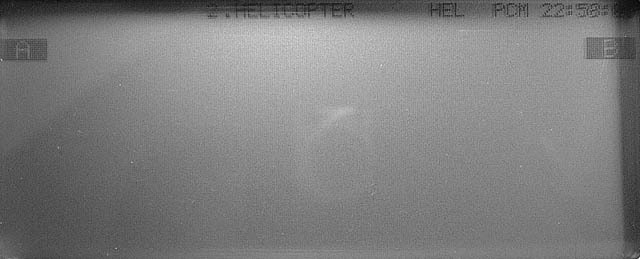
2.HELICOPTER
= Stick Mode 2, helicopter version (T9ZHP)
[A]
takes you to “ID AND TIME” and “SWITCH TYPE” screens
[B]
takes you to every other screen
------------------------------------------------------------
ID AND TIME
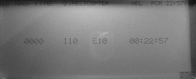
0000
= ID number (password)
I10
= internal firmware version 1.0
E10
= external ROM contains firmware version 1.0
00:22:57
= Total usage time (hours x100 : hours : minutes)
------------------------------------------------------------
SWITCH TYPE
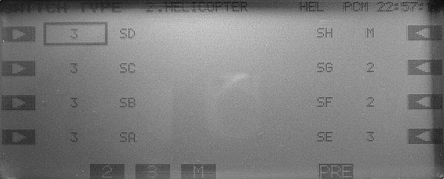
This
screen allows customization of the switch configuration. Obviously physical
replacement of the switch is also required. All types of switches have the same
number of contacts and identical footprint which makes direct replacement
possible.
Select
the switch you wish to modify, then choose between [2], [3] or [M]
2
= 2-position switch
3
= 3-position switch
M
= momentary switch
SA
- SH = Switch A – Switch H
------------------------------------------------------------
SWITCH REV
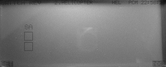
Calibration
process for the toggle switches:
Press
[SET], toggle switch A, press [SET]
(Do
not calibrate the middle position of switch A – if such position exists on
your radio)
Confirmation
of successful calibration:
Both
boxes should become black.
------------------------------------------------------------
NEUTRAL REV
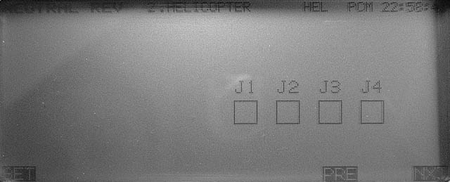
Neutral
calibration process for the joysticks:
Set
all sticks to neutral (centre) including throttle, Press [SET]
Confirmation
of successful calibration:
All
four boxes should become black.
------------------------------------------------------------
WIDE REV
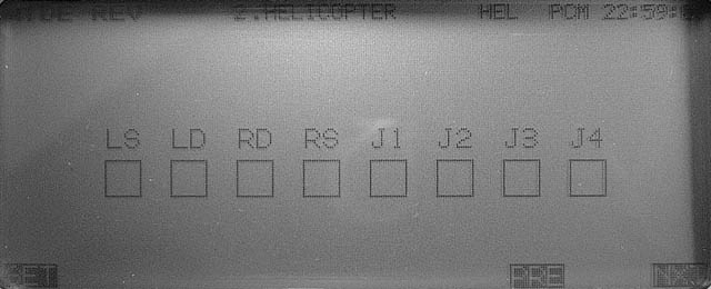
Move
both sticks fully right and fully down, set knobs fully clockwise and sliders
fully down. Press [SET]
Confirmation
of successful calibration:
All
eight boxes should become black.
Note:
These controls can be calibrated individually. Any control that we do not wish
to calibrate must remain at the centre of its range.
------------------------------------------------------------
NARROW REV
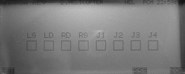
Move
both sticks fully left and fully up, set knobs fully anticlockwise and sliders
fully up. Press [SET]
Confirmation
of successful calibration:
All
eight boxes should become black.
Note:
These controls can be calibrated individually. Any control that we do not wish
to calibrate must remain at the centre of its range.
------------------------------------------------------------
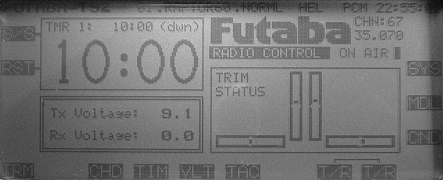
VOLTAGES (calibration)
Voltmeter
calibration procedure:
Two
calibrated power supplies are required.
Set
the battery voltage to 8.5±0.2V and the receiver voltage input (DIN connector,
Pin.6) to 5±0.2V. Press [SET]
Confirmation
of successful calibration:
None
at this stage. However, voltage check is available at later screens.
------------------------------------------------------------
SWITCHES
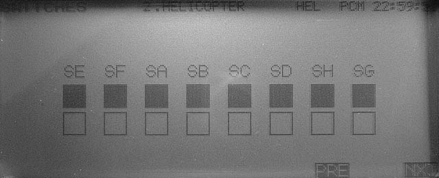
Toggle
switch check. Move switches to all position.
All
boxes should become black.
------------------------------------------------------------
TRIM BUTTONS
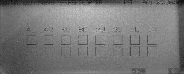
Operate
the trims and confirm that the corresponding box is turned black.
Top
line corresponds to normal trim.
Bottom
line corresponds to fast trim (harder press of the switch).
-----------------------------------------------------------
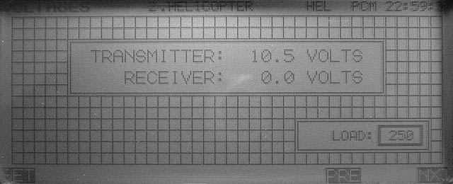
VOLTAGES (check)
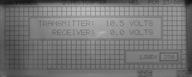
Two
calibrated power supplies are required.
Set
the battery voltage to 8.5V and the receiver voltage input (DIN connector,
Pin.6) to 5V
Confirm
that displayed voltages are within ±0.2V of power supply voltage.
------------------------------------------------------------
TACHOMETER
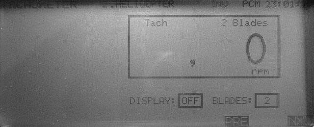
Check
tachometer operation.
Procedure:
Position tachometer sensor near a fluorescent light tube or TV screen (not
computer monitor).
Reading
should be:
3000
± 20rpm fluorescent light at 50Hz (Europe)
3600
± 20rpm fluorescent light at 60Hz (USA)
1500rpm
± 10rpm PAL TV (Europe)
1800rpm ± 10rpm NTSC TV (USA)
------------------------------------------------------------
IO PORT
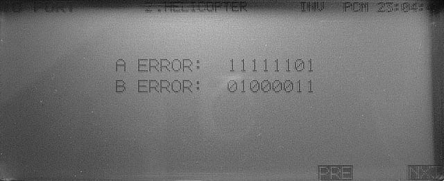
This
is a hardware test that requires some technical knowledge. Here is what these
numbers represent:
LSB
at right.
bit7
= PLL connector, RFCONT pin
bit6
= PLL connector, CLOCK pin
bit5
= PLL connector, DATA pin
bit4
= PLL connector, LE pin
bit3
= CAMPac connector, Pin.2
bit2
= CAMPac connector, Pin.3
bit1
= DIN connector, Pin.3
bit0
= RF module connector, METER pin
All
pins are configured as inputs for this test although some function as outputs
during normal operation. A ERROR indicates the state of these pins when this
screen is entered. If the state of these pins change A ERROR is not updated.
However B ERROR shows ‘1’ for any of these pins that transitioned from high to
low.
------------------------------------------------------------
LCD DISPLAY
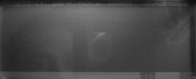
The
big dark section blinks on/off. Confirm there are no “dead pixels” (white dots)
in this area.
------------------------------------------------------------
EDIT KEYS
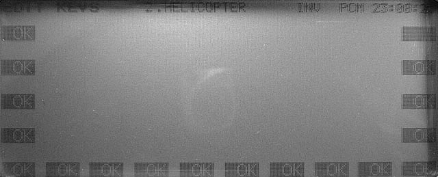
Press
all keys from A to R. The corresponding box displays [OK].
Once
all keys are pressed you will be prompted to exit the service menu or return to
the previous screen.